Some time ago, I repurposed a bus flipdot display. From then I kept an interest on this fascinating mechanical way of displaying information. Some companies such as AlfaZeta or Breakfast continue to produce them. They managed to drive them very fast, making animation possible. Usually, and it was the case for my bus display, all the dots of a matrix are driven sequentially. It is very common that each columns of a dots matrix are flipped one after the other, and for good reasons. Information on these matrices are meant to be rather static, and doing so requires electronics only for each rows and columns, and not every pixel.
If you saw my previous post about the Neon pixels, you probably see some similarly.
Gigantic modern fast flipdot matrices are truly impressive (and very expensive), notably here : https://youtu.be/SJU2-1X8kHQ and here https://youtu.be/VFG1D7lVMiY. There is a nice article on Hackaday. However one can see the driving process.


Some 8×8 squares or larger structures are notably driven separately, giving some artifacts when the animation is fast.
How these matrices are driven ?
There are tiny magnets hidden inside each flat dots. Basically, to flip a dot, you have to flow an electrical current into the coil, generating a magnetic field around it. The direction this current flows will flip the dot from one position to the other. Only a short pulse of current is needed. The electromagnet core stays polarized, keeping the dot on position, even when the power is gone.

Image courtesy eldisrl.com
The common solution to the problem of flowing a current pulse in both directions is using a kind of H-bridge topology. Add two diodes and you can multiplex the dots in a row/column way.
Frederic L made a very extensive explanation of how this works on his hackaday.io project.
And Yann Guidon started as well a Hackday.io project call Dot Flippers, aiming discussions and exchange about using flip dots.
How can we imagine a different way. My aim from here is to drive all the dots of a matrix at once, possibly up to 30 times per second.
Obviously, a driving mechanism should be implemented for each dot. There is some integrated H-bridge chip, but they are quite expensive if you consider one per dot.
After playing a bit with raw flipdots, I observed that a charged capacitor of around 10uF at 16V, discharged directly into the dot’s coil, is enough energy to make the dot flipping correctly. There is something to dig here, so I made a circuit with the coil in series with a capacitor, as shown below. One side is grounded. If you apply a voltage on the other side, the capacitor will charge, with a current flowing through the coil in one direction. If you discharge the capacitor by grounding this same side, the current will flow the other way.

Now how to charge and discharge this circuit? With a CMOS, or complementary Mosfet for example. (Or half H-Bridge…) Lets try to simulate this concept in LTspice:

It seems to work, the green line is the current across the coil. Pulses in both directions are generated, depending on which input is enabled.
A nice feature of this circuit is only the charge will consume energy, the flip back is for free.
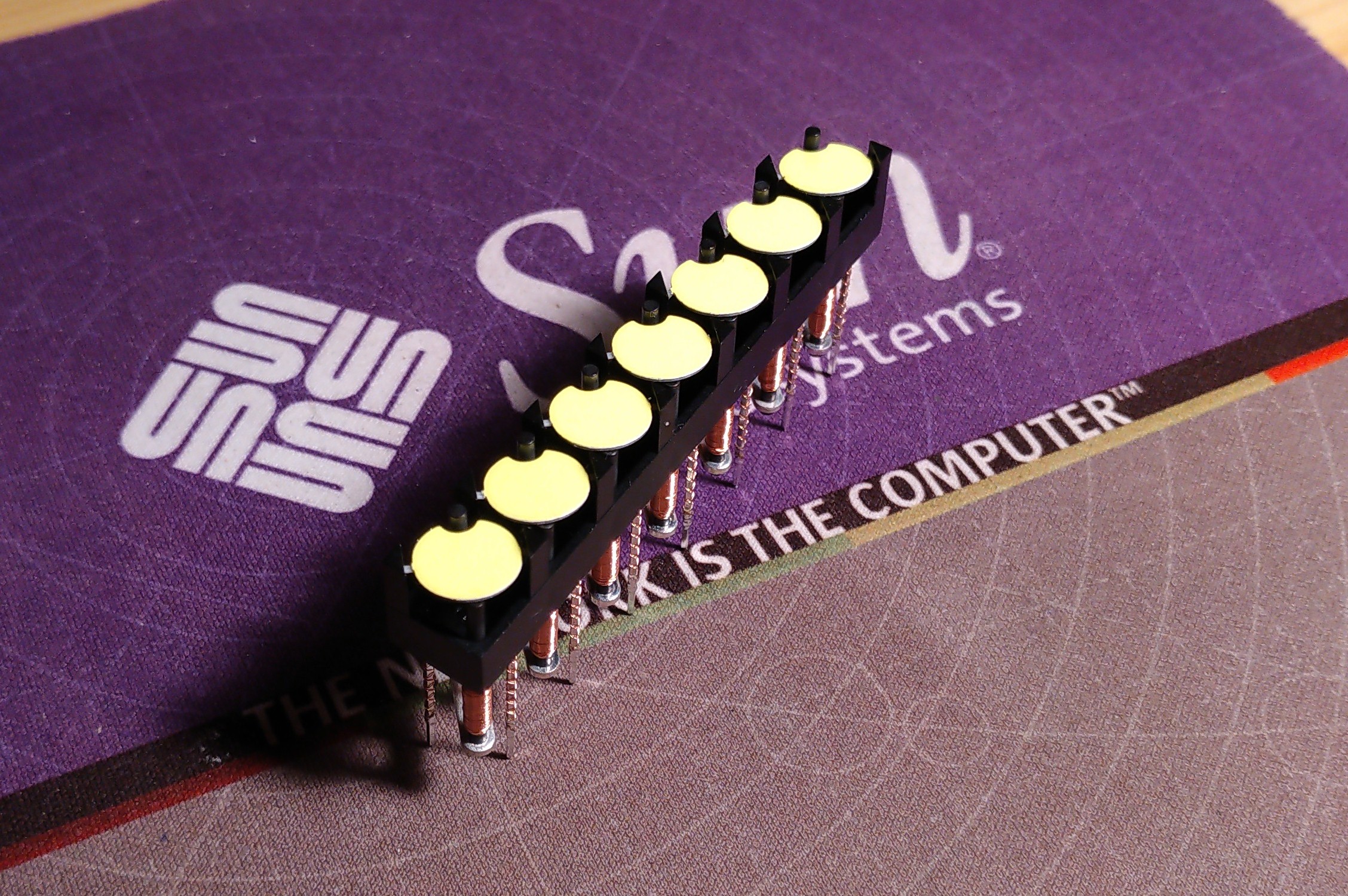
We can buy flipdots here on Hannio.org. They come in rows of 7 dots, probably because of 7×5 fonts.
Lets start KiCad and prototype this idea. We need 7 drivers, a microcontroller and a voltage regulator. I Choose a PIC with a handy SPI peripheral, plus two 8bit port. The PIC16F15355.

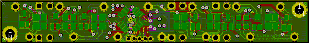
Using a 4 layer PCB, I manage to fit everything within the flipdot footprint.
I ordered the boards from JLCPCB. As usual, I’m very satisfied. The price for 4 layers boards are very attractive, the quality is very nice, and they are in the mailbox in one week.
Now lets try assemble and make a test program.


The only problem I had is some transient negative pulse appearing when I unplug the main power rail. This kills the cheap 5v regulator I first used. With a free-wheel diode connected on the main 24V power supply (it should be max 20V as pointed in the comment! thanks Ken536) and a more robust voltage regulator (MIC5233-5.0YM5-TR), it seems we can proceed with the assembly!
Meanwhile, few purple boards arrived from OSHpark as well. Quality is top notch as usual, the silkscreen is amazingly precise. However the board sides have to be sanded to remove the supports. Too bad the ‘after dark’ option is not available for 4 layers.


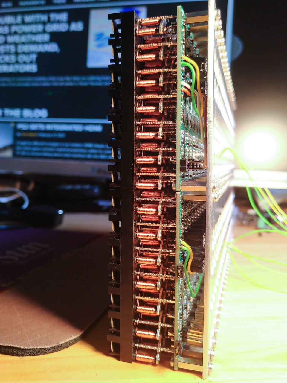
The second Covid-19 lock down, and curfew here in France, gave me some time to solder the 2500 components and program the 48 PIC. I have to admit, having a task where you can focus and with an objective, helped me not going crazy during winter.

Communication is SPI, and all modules are daisy chained exactly as the Neon Pixel modules. However I had to feed the 20V at each ends of the boards stack, apparently the impedance of 48 boards in series is too much and prevent the dots to flip correctly at the end of the stack.
To test this 14×24 matrix, an ESP32 act as a socket server over WiFi and sends the frames on the matrix SPI input. A Java program captures and generate a video flux on a distant computer.
To conclude, I’m quite happy the resulting matrix is so responsive. And I have yet an other adventure planed for this matrix.
All the sources and schematics are on the following github repository : https://github.com/pierre-muth/fast-flipdot .
A small addition to people willing to reproduce this project: calculate the gran total in cost and time. Unless you’d like to experiment this driving strategy, it is probably wise to buy a professional product from AflaZeta.


nice work 🙂
Thanks a lot!
Interesting. I have been playing with a totally different concept, maybe that can be integrated here for even better results?. Basically a current pulse driver, multiple coils in series, but those who are not to be flipped are shorted out by back2back MOSFETs.
Thanks!
That’s very interesting! I’m very curious, did you publish your idea of current pulse driver ?
Whoa! This is amazing!
Pingback: 30 FPS Flip-Dot Display Uses Cool Capacitor Trick – OSH Park
stunning mate
WOW!
fabulous project ❤
Hi, could you update the schematic with the flyback diodes and new regulator? Also what type of cap did you use ceramic?
Hi !
I’ve put the diode on the main 24v power supply side. The new regulator is a MIC5233-5.0YM5-TR, which has the same pinout. I’ll update the kicad asap.
For the capacitors, it is a stack of two ceramic of 10uF 25V package 1206 : MC1206X106K250CT. It is important to take a low serial resistance capacitor.
Pingback: Paint by Numbers [Maker Update] •Maker Project Lab
I’ve been wanting a flip-dot display for ages and think this is one of the best implementations I’ve seen so far. I’ve already ordered some boards and have started to assemble and program them. I was wondering if you’d consider explaining the code and a how they communicate over SPI in a bit more detail. As far as I can tell, everything is functioning fine but I’m not clear on how everything works. Thank you for sharing your work so far, I’ve found it very fun and interesting.
Hi Robert,
Thanks a lot for your nice comment! Not sure if it’s the best implementation, but I thinks this capacitor method was not yet applied to flip-dots. For example, a multiplexed row/column driving is more cost effective.
You’re right, I should try to enhance the blog post regarding the programs. Meanwhile I’ll try to summarize below:
The PIC program just takes the incoming byte on SPI to set the dots, the 8th bit is just ignored as the there is only 7 dots. When it receives data, it push the previous byte on the output, in order to shift it to the next board. To refresh all cascading boards, you have to send as much bytes as boards, to the first one. Doing so the first byte you sent ends up into the last board. It works on the same principle of the adafruit ‘neopixels’. To latch the data and make the boards refresh the dots, it must have pause of minimum 2ms.
So, if you cascade 10 boards, send 10 bytes to the first and wait at least 2ms. Then all the 10 boards should refresh.
In theory, the OPT1 in and out are the same but with serial at 115200bauds. But I didn’t test this very much. For this reason you might observe instabilities if OPT1IN is left floating. (I didn’t have this issue)
I realize the board markings are not very clear. You can get everything with the schematics of course. On one side, there are the inputs: 12v, GND, CLK, DATA, OPT2, OPT1. And the other side are outputs: 12v, GND, CLK, DATA, OPT2, OPT1. The two GND pins are connected, same with 12v pins.
The power supply should be higher than the 12v I wrote on the board, as 12v is a bit low to flip reliably the dots. Components should be rated to work with 24v. As the power pins are connected, better to put your power supply cables on as much board as possible. I observe problems if I connect 20 boards in series and only provide the power in one end. For the matrix I did, I cabled the power one each ends of the 2 rows (4 cables). It is certainly an impedance effect that prevent to charge all the capacitors so quickly.
Hope that helps, and of course don’t hesitate if any question.
Have a nice day !
Pierre
The components are rated for >24V, but the VGS of the mosfets is max 20V, pulling the gate low will exceed this limit. It seems to go fine though?!
Wow, you’re right! I switched so many times between components that I missed/misread/overlooked the DMG6602SVT datasheet ! My original plan was to rate everything up to 24v.
I don’t know how long it can survive at 24v then. Better stay at 20v max.
Thanks a lot for pointing it !
(I’m editing the post)
I’m happy that I can help you!
After seeing your project I really wanted something like this. I did make my own boards but with your capacitor trick. My board carries 5 flipflop modules and uses one small micro (STM32) and 9 shift registers (HC595).
Some of my dots look like they are sticky, they will rotate after helping them. I hope increasing the voltage will help them a little bit. (I’m at 12V now, but maxed to 16V because of the MCP1703A)
Hi Pierre,
Thank you so much for your detailed reply. This clarifies a lot of questions I had. I have only built three boards so far but as soon as I have the spare time I intend to finish the batch. I will keep you updated and I’m sure I’ll have more questions. I’m new to hardware development but I’m having a lot of fun with this project. Thank you for sharing your knowledge and I look forward to more projects from you in the future.
Best wishes,
Rob
Pingback: Flipping dots … gently | About using electronic stuff
Hello Pierre,
I find the implementation of the flip dots ingenious and would like to build me also one like yours.
Unfortunately, I have not much experience with soldering also not so much with the manufacture of PCB, so I would like to have the complete PCB assembled. I thought of “PCBway”, they also offer double sided SMT.
I have looked at the schematics in Kicad and have a few questions about them. Also I have to complete the generated BOM list.
Q6,Q8,Q10,Q12 with the part RJU003N03FRA and the footprint dot_flipper:SOT-23-small is given in the Pcbnew view as footprint : SOT-23-wide with the value BSS138.
Can this footprint simply be taken over with the component RJU003N03FRA?
Which capacitor for C10 and C9 is suitable?
Anything special for R21,R20,R19,R18,R17,R16,R15,R14,R13,R12,R11,R10,R9,R8,R7,R6,R5,R4,R3,R2,R1?
I would greatly appreciate your help.
Hi Michael,
Thanks a lot for the nice words !
It would be very nice if you manage to get the board assembled !
You get good questions indeed:
Pay attention, The Q2, 4, 6, 8, 10, 12, and 14 are not SOT23. They are SOT323 (or SC70-3, or UMT3), which is smaller.
C9 and 10 can be any 0.1 to 1uF, 0805. Same for the resistors.
Pay attention to C1, 3, 5, 7, 9, 11, and 13. To lower the internal serial resistance, I had to stack two 10uF on to of each other. The tests I made with single 20uF capacitors results in not reliable flipping. It might work on your case, but be prepared to re-solder a second capacitor on top of the assembled one.
Anyway, don’t hesitate, and have a nice day,
Pierre
Thanks for your reply and helpful tips. I am trying my best to make appropriate adjustments to the PCB. Would you mind taking a quick look at it? I will upload it to your github repository. But it may take some days….
Many greetings
Michael
No problem, I will have a look. Take the time it needs.
I remember I tried to maximize the track width for Sources of the complementary FET (P and N channel), in the hope to reduce impedance. That’s why the filled zone on the top is the +16V. Also, I’ve put a wide track on one inner layer that connect the two 16V in/out pins, as the boards will be chained, all the current will flow through the first one. This could have been even wider. I had to feed the 16V not only on the first board, but also the last one.
Good luck ! I hope you’ll manage to get a nice matrix !
I have been looking to get me some flipdot displays, and this seems like the perfect candidate.
What you have done on them is wonderful work.
It seems they are out of stock at HannIO, would you happen to know somewhere else I could get these at reasonable prices?
Thanks for the comment and your nice words !
Unfortunately, HannIO was the only web site selling bare dots to individuals I found.
For panels of flip dots, and to my knowledge, there are two other solutions. A used one from bus or tramway, or get a new one from AlfaZeta. The price is always painful, they are complicated to build though.
Hello Pierre, luckily it seems that I could order the last flip dot modules from HannIO (5x7x10 dots in total):-) They will be delivered tomorrow. Meanwhile I took a closer look to prepare your pcb for the abbiltity to get all components assembled from the manufacturer.
– So I changed the footprint of RJU003N03FRA mosfet in schematic to fit SOT-323. I think that the pins 1,2,3 are labeled different for sot-323(see https://fscdn.rohm.com/en/products/databook/datasheet/discrete/transistor/mosfet/rju003n03fra-e.pdf), so I changed the pins in the symbol library. I don’t no if this makes any difference for pcb assembly, but I don’t want to confuse the manufacturer.
– For Stacking two capacitors together (you took MC1206X106K250CT) I found these capacitors from kemet (https://www.mouser.de/pdfDocs/KEM_C1108_KONNEKT_X7R.pdf) On page 6, first partnumber: C2220(a)206(b)5RLC(c) 20 µF 206 50 V. Could these fit? Could this be an alternative?
I will soon upload my modified files to github.
Michael
Hi!
You’re right, better to correct the footprint numbering!
Great find for the stacked capacitor! I didn’t know they can come like this. Check if the footprint can match.
Good news you can order the flip dots!
I will try to rebuild some segments, and check all the steps to program the PICs. I remember I’d like to add something on the code…
Thanks for being so motivated, hope it will not cost you more than you planned.
Cheers!
Hello Pierrre,
a while has passed and I have finally uploaded the finished Kicad files for the assemby. For this I created a fork on your github project:
https://github.com/MKdent/fast-flipdot/tree/main/dot_flipper_assambly
DRC seems to fit. Maybe you can have a look at it and check if it’s correct.
In the meantime I was also able to get your java program running. After that, I was a bit worried that I wouldn’t be able to get the PIC16F15355-I-MV to work or that I wouldn’t be able to manage the data stream…
But I was so fascinated by your idea that I looked for further solutions. And here is my idea on the subject of flipdots. Why not use a ws2811 that also controls all the LED strips? After some preliminary considerations, I had a PCB assembled and lo and behold, it works 🙂
https://github.com/MKdent/FlipDot-ws2811
The next step is to reduce the size of the PCB and then assemble the display.
If that works, I’ll put the schematic and BOM together on github.
So thanks again for your inspiring project!
Hello !
Nice to ear about your progress ! I quickly check your dot_flipper_assembly.kicad_pcb and I don’t any mistake. Thing is to maximize the width of the power planes/track to reduce impedance.
I considered using WS chips, but I think I lost myself in reducing the components 🙂 Your implementation seems to work quite well ! I would be worried during the transition between the flips, but apparently it is robust enough to never turn on both transistor at the same time. Kudos ! And it simplifies a lot the driving by the ESP32.
Before I manage to squeeze everything within in the 10x70mm flipdot footprint, I considered put the board perpendicular, and plug the boards in a back panel to make the matrix. So maybe it could suite you as the board might be larger.
Looking forward your next steps !
Hello Pierre,
It takes time, but I’m on the ball. Here is a small update. I think it works so well now that I can assemble a small display. I had to change a few things in the circuit diagram. I will write this down in more detail soon. https://youtu.be/ZCjcpKwgIRs
Best wishes
See you soon!
Waw hello Michael !
This is a major milestone ! Kudos, it seems to be very responsive !
Looking forward to see a display assembly !
Thanks a lot for the update !
if i may ask, how did you accomplish driving the dots on the bigger matrix, so many lines to switch.
Hi!
The matrix I’ve built is 14×24, besides the driving boards attached to each group of 7 dots, the image is transmitted with and ESP32 using SPI.