Several years ago I had a challenging combo in mind. Giving a try to astro-photography while not ruining myself.
 I didn’t start with nothing as I would like to use my camera, a full-frame DSLR with a variety of lens. I don’t have any experience in astro-photography, then I bought the Orion Mini-Eq, a beginner tabletop equatorial mount for camera, plus a small DC motor. But I didn’t manage to get decent shots, and the mount start to be dusty.
I recently focus a bit more on this subject and I tried to improve myself on two key ingredients. The orientation and the motorisation.
The main axis of the mount should be precisely set parallel to the Earth rotating axis, in order to compensate this rotation with the motor. This will enable taking long exposure picture without start trails.
Orientation
In the north hemisphere a good approximation is to target the polar star (Polaris) to align the main axis. But it implies, in my case, to set the second axis precisely to 0 and have the star in view. The markings on this mount are not really helpful and Polaris is visible only on one side of the house. So I printed a plate with a cylinder that fits in the bottom tube of the main axis. It is precisely at 46.28 degrees, the latitude of my place.
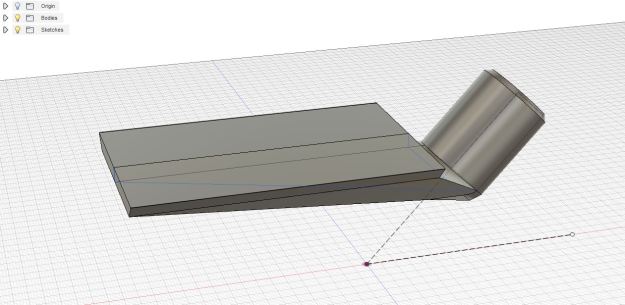
On this plate I can put a bull’s eye bubble level and a compass (or a phone). It is not perfect I imagine, but it helps me learn.
Motorisation
The main axis rotation speed should be one turn per day, the same as the Earth.
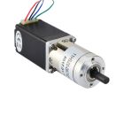 I found on eBay some stepper motors with a gearbox. The gear around the Eq-mount divides the rotation by 100 already, so adding a 1:100 gearbox on the stepper side divides it, in total, by 10’000. There is 86’400 seconds in a day, so the stepper motor speed should be 8.64 seconds per turn. This gearbox has a compact planetary gears arrangement.
Controller
 I choose the famous TMC2130 stepper motor controller, mainly because the silent StealthChop mode promises a smooth rotation. In particular the Silent-Step-Stick board of Watterott/pololu, that simplifies the wiring.
An article in hackaday describes in detail how these controllers work. This time I would like to have something useful rapidly, I then took an ESP32 with the arduino framework. I could just plug libraries for the TMC2130 and for a small LCD character screen.

The ESP32 has to send pulses to the stepper motor controller, corresponding to the steps we want to generate. The motor has 200 steps per revolution, and the controller supports 256 micro-steps. It means we have to generate 51’200 pulses per motor revolution. We saw that the motor has to spin at 8.64 seconds per turn, so it gives 5925.9 pulses per seconds.
Coming from tiny 8bit micro-controllers, I first used a timer of the ESP32 to generate the pulses at a precise time interval. The ESP32 has timers that can be set down to the 80Mhz clock and the counter it on 64bits, which is quite remarkable. I set the prescaler at 80 to count micro-seconds, and the counter to 1687 in order to generate interrupts 5925 times per seconds. On the interrupt routine, we just flip high and low the step pin.
However I didn’t expect that the generated pulses don’t have a stable period. I naively forgot the ESP32 arduino framework probably relies on RTOS, thus some interrupts has greater priority than my timer. The period time in average is correct of course, but the period varies pulse to pulse.
After some googling, it was obvious to use the PWM instead. Everything is there with the ledc() function, and can be set with a 0.4 Hz resolution. I measured the pulse period difference between timer and PWM method :

Enough confident after this success, I just add three buttons to change the digit values of the output frequency, and the rotation direction. Also an option to stop the motor, it should not spin when the power is cut.
Next step is to make a basic case to put everything inside, my awful wiring don’t deserve public views.


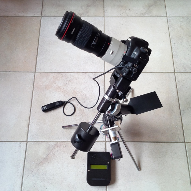
And finally, I attached the motor on the Eq mount.


With everything attached, the system looks like that:
The two following pictures are single frames, quickly processed from the raw camera files. Bellow is the Orion nebula, the tracking speed is not perfect as the stars still make trails. The theoretical value of 5925Hz micro-step frequency is certainly off due to the ESP32 oscillator real value. The exposure time is 60 seconds.

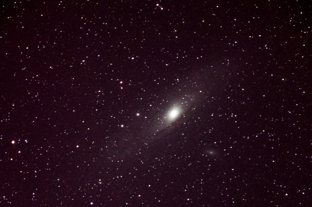
Bellow the Andromeda galaxy, 60 seconds as well but with corrected frequency, hence a better tracking.
Conclusion
I have now no excuse for waiting a clear night and start learning picture stacking with advanced astro-photo softwares !
You can find the arduino code and the 3D files here on github: https://github.com/pierre-muth/QuickEqMountController

