INS-1 / ИНC-1
Fortunately, these single dot tubes are still easy to find in large quantity and rather cheap. Made by Gazotron, it seems they buildup a large stock at that time. The INS-1 has the advantage to be small and produce a nice dot due to the lens-style front. Plus its striking voltage is maximum 100V, lower than regular Nixies.


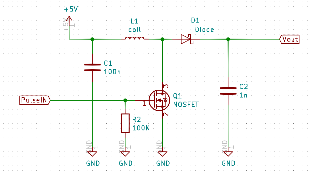 At first I imagined 5×7 dot character modules, such as the TIL305, but bigger. While playing and trying to make a tiny and simple 5V to 100V step-up power supply, I realized how simple it can be. Here we just need to reach the striking voltage and only 0.5mA. As there is yet non uniformity in brightness between tubes, no strong voltage accuracy is needed. Without the signal generator, it is a diode and a coil, shorted to ground with a transistor at high frequency.
Then comes the idea to mimic the popular serial cascading LEDs, such as the WS2812 or SK6812, the so called Adafruit ‘NeoPixel’.
Neon Pixel
What I observed when I was empirically select the components is one key parameter to reach 100V is low resistance coil and mosfet. The voltage can be adjusted by choosing the pulse frequency and width.

I was happy to see that only few pulses are needed to reach 100V. This enables pwm for bulb brightness control directly by driving the transistor. It is achieved with a pulse frequency of 100KHz and a PWM of 500Hz.


This leads me to the microcontroller choice. The peripherals needed are SPI, PWM, Timer, NCO and logic cell. The cheapest with all these options seems to be the PIC16F15313.

I first have issues with the SPI daily chain propagation delays. The data takes some time to be clocked out from input to output. If we use the same clock line for all the devices, the data will quickly be out of phase in respect to the clock.
A workaround is to delay the clock as well on each devices, and have in one side a data and clock in signal, and on the other side a data and clock out signal. Fortunately, this PIC has 4 logic cells, so I can use one to delay the clock, like a line buffer. I was lucky that the logic cell delay is almost the same as the SPI logic.
The only problem remaining is the rise and fall edge detection, they are apparently slightly different. It results a kind of clock pulse stretching, a change on the duty-cycle. However I can deal with it. With a clock speed of 480KHz, the 384th device is still receiving a usable clock signal.


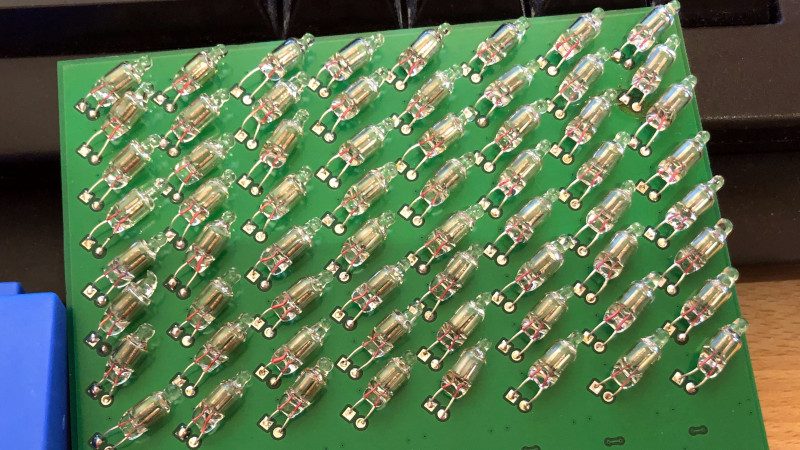
Now that the prototype works, it is time for a PCB. The aim here is of course to have the smallest footprint, while keep connections at the opposite of the bulb.


I ordered the boards from OSHpark and JLCPCB. Both make very nice boards. OSHPark has the gold finish, and JLCPCB has the V-cut option, which is very convenient in my case.


Lets start the long journey of soldering, The 2020 lock down gave me plenty of time to solder the 384 boards, on which there is 11 components.


A matrix
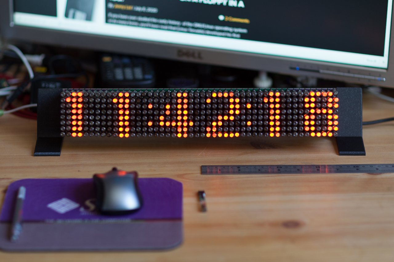
Meanwhile, it is time to think about a usable display. I then made matrix blocks of 8×8 pixels.


And controlled by an ESP32. I got the first encouraging result.

I start to make a support as well. A simple aluminium plate with two 3D printed legs. I add several slots in order to choose the inclination.


Coding
I’m using an ESP32, with the arduino framework, and the Platform.io IDE. The nice thing is I could extends the AdafruitGFX lib. So all the work of drawing, fonts etc, is yet done.
I added the notions of display size and buffer size. With a bigger buffer size, I can make easy scrolling by changing the coordinate of the view frame.
This Github repository contains the code and the schematics/PCB.
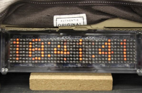
Coupled with Andy Geppert Core Memory kit:
Conclusion
With around 20mA per pixel, at full brightness, the total of the 384 pixels is almost 8A. Everything is at 5V, so around 40 Watts is needed when all pixels fully on. Everything then is powered by a 10A 5V power supply.
This is the reason I’m keeping the display open, that way an airflow exists between the pixels and everything is kept below 40°C.
It is not the first matrix made of neon bulbs, here is a nice modular one made by Robin Sterling. (@RC_sterling) :


And an other one by @cronos_sv spotted by dangerous prototype at Tokyo Maker Faire 2013.
Recently Manawyrm Made 8×8 chainable matrices, featured in an atricle on hackaday:


Pingback: Neon Pixels Matrix Display Clock - Electronics-Lab
Great work! That is quite a project… 8 amps at full load! I’m sure it will keep the room nice and warm during winter too haha. If you like neon things check out my site too! (neonkev.com).
Since you were generous enough to share the pcb artwork and code… I may just have to build this project as well!
Thanks a lot !
Very nice work on your website ! Love the Panaplex and B7971 !
Pingback: Fog Cutter [Maker Update #189] •Maker Project Lab
Pingback: Driving Neon Pixels with an ESP32 « Adafruit Industries – Makers, hackers, artists, designers and engineers!
Wow, I really liked this. I’m going crazy because I want to make it in personally.
Can you tell me how much and how long it took to proceed with this project?
The price of nearly 400 MCUs is burdensome. I wish I had a better choice.
Thanks !
Yes the price of micros make this an expensive project. Be sure to check the total price before starting to avoid bad surprises.
If I remember correctly I managed to complete the assembly of 5 pixels in one hour. I had the small boards in V-cut panels, I kept 5 boards attached in a row, and then solder all the components by hand. Then detached them, solder the pins and the bulb, them program the PIC.
Don’t hesitate if you have any question.
Instead of using a separate MCU for each neon bulb, how about attaching a step-up converter as many as the number of neon bulbs to the output of a dot matrix LED driver component such as a SIPO shift register or IS31FL3733? If use a timer, I think can change the brightness of individual light neon bulbs.
Hi,
Interesting idea, do you have yet a design of a 5 to 100v step-up converter you would attach to each bulb ?
The problem with LED matrix drivers is each led is ON only a fraction of the time. (1/12 for the IS31FL3733 for example). The INS1 neon bulb brightness is far less than a LED, thus dividing it by 12 will grive a quite low brightness display.
There are numerous solutions to achieve such a matrix (I’ve put some other at the end of the post). The main purpose here was to mimic the serial chain of WS2812 like leds.
Hope it answers your question, cheers!
Pingback: A cute little single tube Nixie clock. | About using electronic stuff