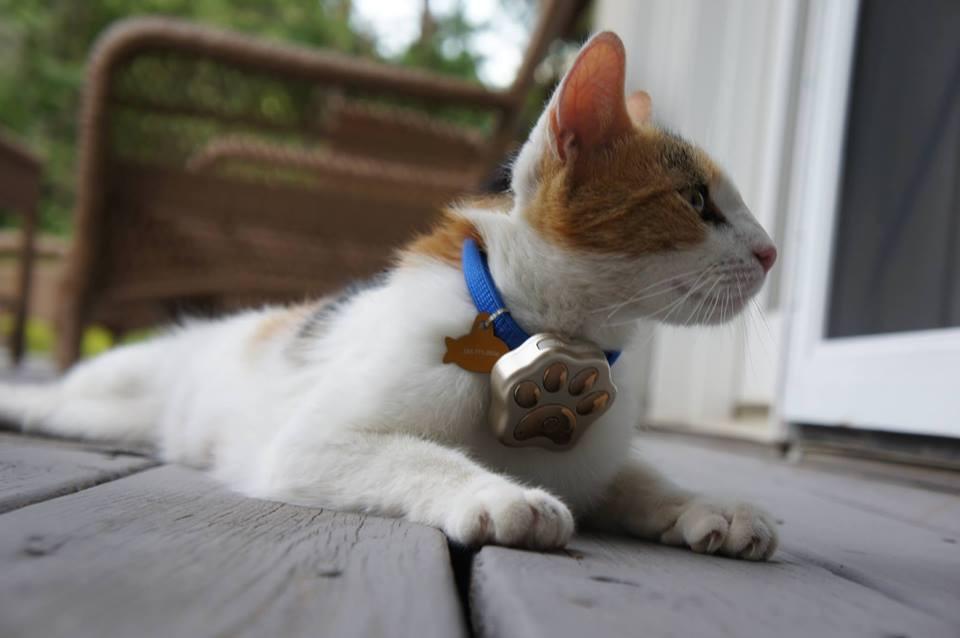
 Mio is a tiny female cat, with a rather independent and proud way of life. She spends quite a lot of time outside doing… well… important cat stuff, among proving her duchess status to the other neighbor cats. However, she never misses us, each evening after work, when we come back home. She can enter the warm house in order to get the well deserved food and attention.
Until one day. And the day after.
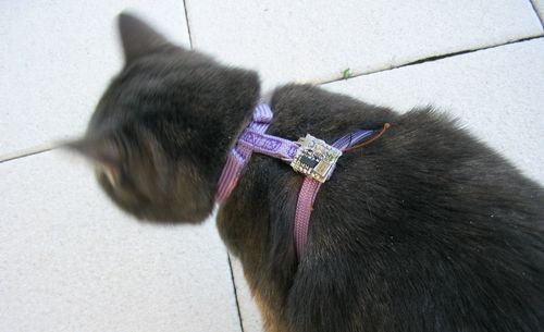
It affected me far more than I could expect, but fortunately the worst things I started to imagine were false. Mio came back home. We conclude she might be being locked by mistake in a barn from the neighborhood. That’s where started the idea of a small RF beacon for Mio. It should to be very small, at least a month of battery life, and can enable a kind of search with a receiver.
What exists
I usually enjoy to think about and make solutions by myself, but what exists yet on the market ?
thepawtracker.com
There are some expensive modules that combine GPS and GSM. Usually they come with a subscription (monthly fees) and you get the beacon location from a website. The few days of battery life is problematic, and they cannot be realistically attached to a small cat due to their size.
Some bluetooth tag seems to have some success. They are small and have a long battery life. These tags have however only a 10th of meter range, and some relies on the proximity of a smartphone, with the special app’ installed and running…
 Finally, over internet I found a very interesting article of someone having the same concern. (https://www.f1nqp.fr/articles.php?lng=fr&pg=144 in french). I’m less confident with analog RF electronics. In addition, the size of the antenna wire is not very confortable. However this solution should be kept.
Exploring RF modules
I discarded the modules working at wifi frequencies (2.4GHz) for two reason. Maybe I should come back here later, but with a coin-cell battery budget, these frequencies are absorbed easily by walls.
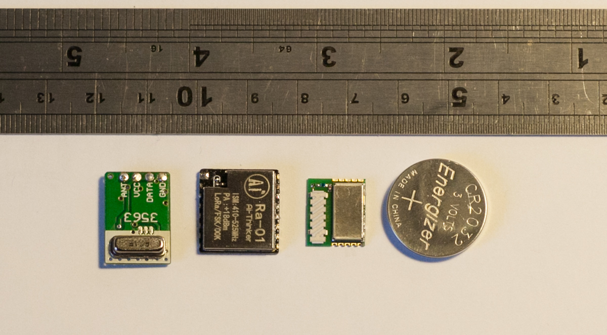
I made some tests with three different RF modules. From left to right:
1 – A basic 315Mhz transmitter
These modules seems to meet the low power requirements. I can even use a TV usb dongle as SDR to receive and find the beacon. The difficulty comes from the antenna. A 1/4 wave antenna for 315MHz is 23cm long. If I spool the wire inside a small case, it makes a coil and degrades dramatically the antenna impedance/efficiency. So the range goes down to something like 10 meters.
2 – Lora module based on SX1278 at 433MHz
These LoRa modules are amazing. They have a really huge range, more than 500 meters. But the problem is still the antenna at 433Mhz. If I use a simple wire, wrapped in the case, I must increase the output power to the maximum (~+17dBm). Then the battery dies after a day. Mainly because the peak current is up to 100mA, thus not suitable with coin-cells.
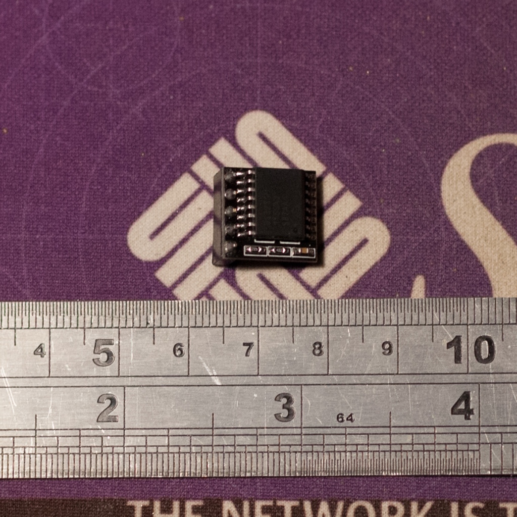
3 – ST electronics module base on SPIRIT1 at 868Mhz
The ST SPSGRF module integrates the antenna, in a very small board. The power consumption is very interesting as well, so let’s go a bit further with them.
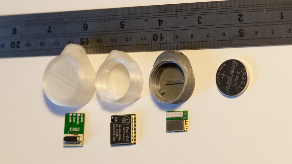
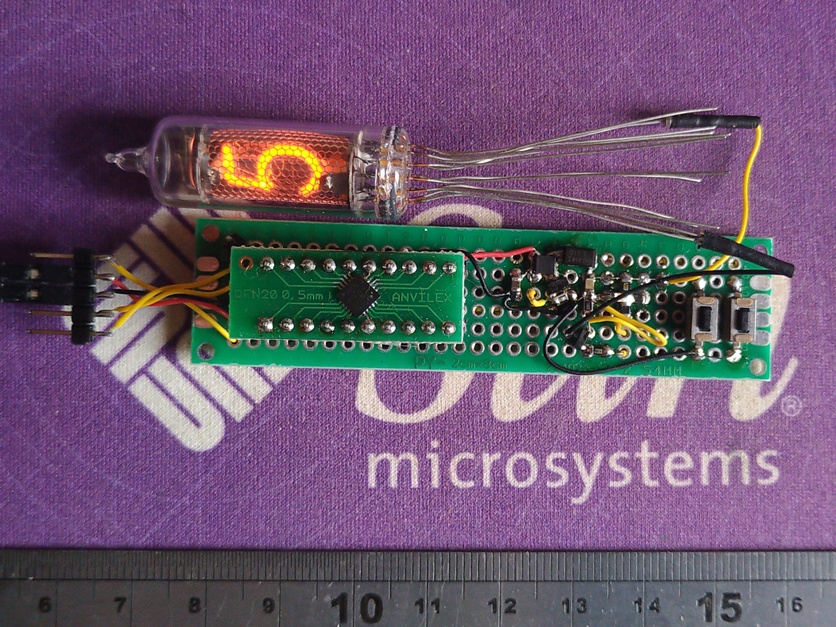
For each module, made a draft case. I choose a small PIC12F1822 in SOIC package to drive them.
ST SPIRIT1 tests
The PIC code basically setup the module and send a message every minute. Fortunately, in addition of the numerous application notes, ST provides a little application (STSW-CONNECT9) to generate dthe setup C code of the Spirit1. It is very convenient as the registers are quite numerous. The message sent is just composed of the battery voltage and the battery voltage drop during the RF broadcast.
The 3D drawing is done with Fusion360. To make the case waterproof, I used neoprene glue on the outside join between the cap and the body. With the screwdriver tool that fits the pattern on the cap, there is enough torque to tear the glue appart to unscrew it. I had to pay attention to not cover the antenna with the coin-cell battery. Event shifted like that, I’m sure it reduces the transmission efficiency.
Receiver and integration
On the receiver side, one interesting feature of the Spirit1 is the RSSI value – in received signal strength. It not gives an absolute distance between the two modules, as it is greatly dependent of the obstacles, but it rather gives an idea.
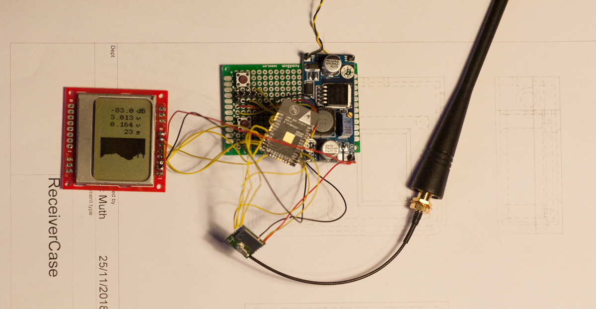 I used the ESP32 on this side for two reasons. First because there are nice libraries for the RF module and different screens, and because I would like the wifi connectivity. With wifi, I can connect it to my logging station and observe the evolution of the signals. I had a PCD8544 LCD, pretty much enough to display few values and a small history chart. The screen on the receiver let me take it outside and try to locate the signal. It displays RSSI, voltages, and a countdown in order to knows roughly when the beacon will emit.
The PIC code, the ESP32 codes and 3D models are on this github repository: https://github.com/pierre-muth/RF-cat-beacon
From the tests I made, the range is around 100 meters. I had the receiver outside in the village, while the cat is (sleeping) in the house (which has half a meter thick walls).
I have now additional logged data channels, I can observe the trends of RSSI and battery voltage on logging station.
Conclusion for now
I need to wait more to conclude on the battery lifetime. Over the last 10 days, the voltage seems constant at 3V. I could increase the transmission rate if possible.
I’m not sure about the reception range, is it enough to locate the beacon by walking around in the village? That’s why I should continue to study the other solutions. For example, I just saw it exists 433MHz ceramic antenna as well. Maybe it enables the use of the LoRa module at low power. They are still interesting as their modulation scheme makes the reception very sensitive.
Thanks for reading and take care of your cat.


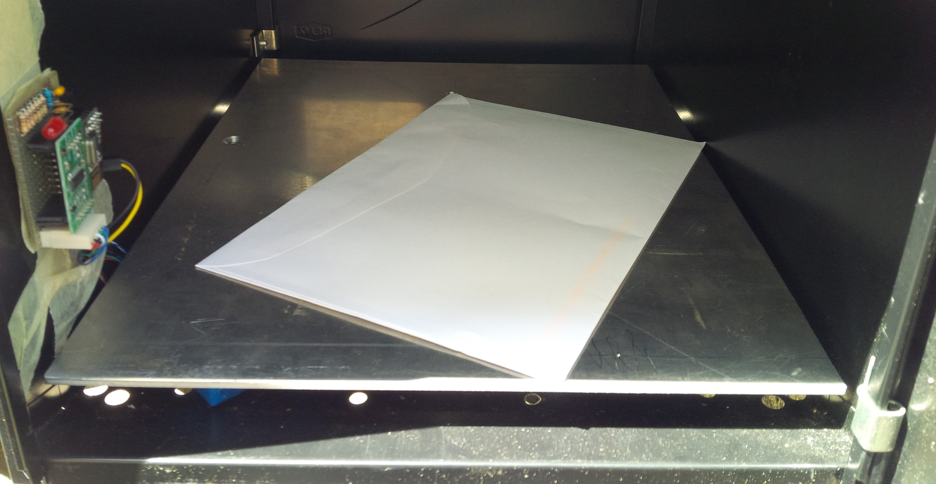
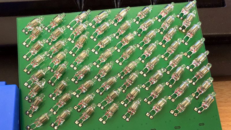
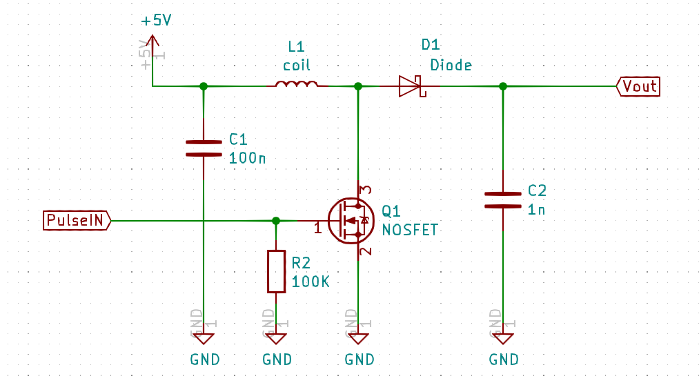 At first I imagined 5×7 dot character modules, such as the TIL305, but bigger. While playing and trying to make a tiny and simple 5V to 100V step-up power supply, I realized how simple it can be. Here we just need to reach the striking voltage and only 0.5mA. As there is yet non uniformity in brightness between tubes, no strong voltage accuracy is needed. Without the signal generator, it is a diode and a coil, shorted to ground with a transistor at high frequency.


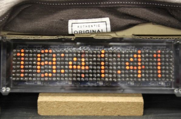

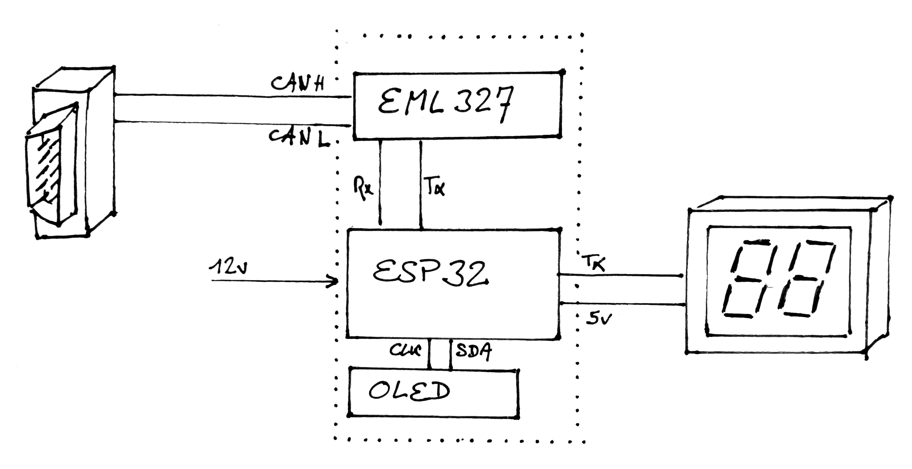
 I could use a GPS module to have the car speed, but I think there are two disadvantages. First, we loose it on tunnels, and second I’d like to show what I’m reading on my dashboard.